Kaatskit Radio Company
Capacitors
In older equipment, a common failure point is the electrolytic capacitors, especially the audio coupling capacitors. Sometimes they fail with a short, but more often, they dry out, become leaky, and gradually lose capacitance with age. The board just seems to sound worse as it gets older. So we send it out for reconditioning, which is usually to replace all of the electrolytic capacitors, and it sounds like new again.
We can't solve that problem completely, but we can make some improvements.
We don't use surface mount parts, so they can be replaced when the time comes.
Our coupling capacitors are non-polar or “bi-polar”. This reduces distortion and makes them last longer.
The usual polar capacitors rely on having a few volts DC across them to maintain their capacitance over many years. The usual op-amp circuits do not provide the needed polarizing voltage. While operating, the DC voltage across the coupling capacitors is nearly zero. Actually, it can go either way, so some of the polar capacitors are polarized the wrong way.
More significantly, even though the DC voltage is small during normal operation, there are large voltage swings when power is turned on and off. It can also happen in normal use. Any signal that drives the amp to clipping can put a big voltage across the coupling capacitors. Somebody bangs on the microphone, or drops the needle on a record. This can be as much as the total rail-to-rail voltage, in either direction. Designers usually don't pay attention to this.
They seem to work fine when they are new, but gradually they fade away.
Now, let's look at how they sound.
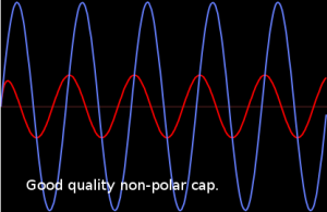
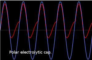
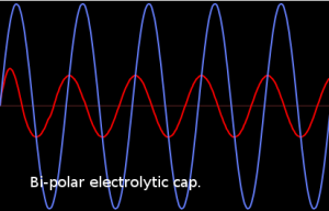
For all three examples, the circuit is a simple first order high pass filter, like the usual interstage coupling capacitor. Series capacitor, shunt resistor. The blue waveform is input, the red waveform is output. As you can see, the output is lower in level and is phase shifted, compared to the input. This is what is expected of a high pass filter. Comparing the three, the only difference between them is the type of capacitor.
Polar capacitors are significantly nonlinear when the DC bias is close to zero, especially when the voltage across goes both positive and negative with signal. They have very high leakage when reversed. You might think of it as being like a diode across the capacitor. As you can see, this can add significant distortion on very low frequencies. It is tempting to use tantalum capacitors instead of aluminum for longer life, but they are more nonlinear so the low frequency distortion is worse. Putting this in perspective, it's really only the very low frequencies that are being partially filtered by the capacitors. You may hear it as a change in sound of deep bass, or you may not notice, which is why the competitors get away with it.
In new equipment, you only see this at very low frequencies, around 1 Hz or lower. As the caps age, capacitance decreases, nonlinear leakage goes up, the cut off frequency goes up, the bass response becomes weak and distorted.
We use “bi-polar” capacitors that are designed for this type of circuit, with a sufficient voltage rating. They cost a little more, but they don't fade away like the polar capacitors, and they have less distortion.
When we can, we use capacitors rated for a higher temperature and longer life. Most of the caps we use are rated for 105 degrees C, instead of the usual 85 degrees C. Again, it costs a little more, but the longer service life is worth the extra cost. Also, they are “through hole” mounted, so they can be replaced easily when the time comes.


